Ch341 Usb To Serial Driver X64
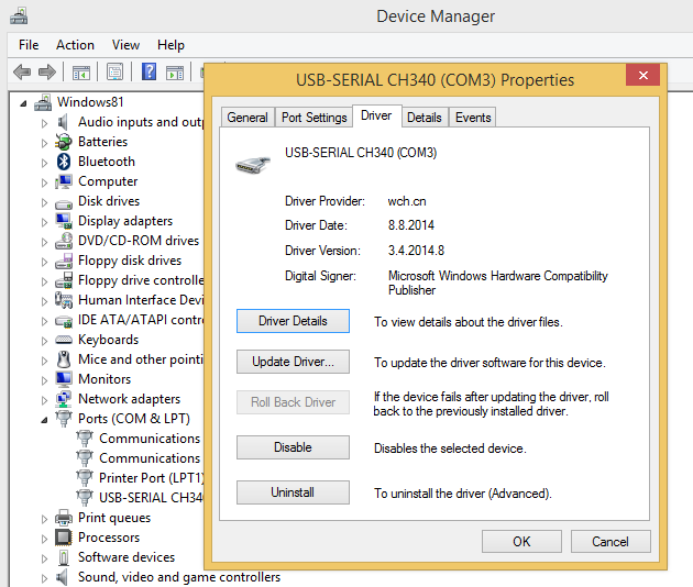
Ports - wch.cn - USB-SERIAL CH341 Drivers Download - Update your computer's drivers using DriverMax, the free driver update tool. Update your computer's drivers using DriverMax, the free driver update tool - Ports - wch.cn - USB-SERIAL CH340 Computer Driver Updates.
Martin hey guys does anyone know why this is everything is hooked up?? Sketch uses 1,030 bytes (7%) of program storage space. Maximum is 14,336 bytes. Global variables use 9 bytes (0%) of dynamic memory, leaving 1,015 bytes for local variables. Maximum is 1,024 bytes.


Ian Culley Thank you greatly for this solution, it works. I run Windows 7 64 bit and was trying for 5 hours (embarrassingly so) to communicate with an Arduino Nano V3.0 purchased on line before I discovered this post.
The trap for young players was not looking specifically at/or identifying the USB comm’s chip on the board earlier on. I fell for the surf the net here is the recommended solution for you. As soon as I had retraced my steps all the way back to the start and Identified the WCH340G chip is used for the comms I was straight onto this web page and downloaded the driver software. Following installation I was able to communicate with the nano and write code to it. I am using a USB cable from a cannon camera that I bought in 2004. As a further test I changed the delay time on the ‘blink’ code and uploaded it to the nano.
So thank you very very much. Randy Moore I have also found that these drivers work fine when connecting the LoLin NodeMCU V3 to my Windows 7 PC (I had to do nothing, since I had already loaded the drivers for my cheap Chinese Arduino Nano clones). I suspect the same will be true for the Amica v0.9 (yellow or blue PCB) NodeMCUs (both considered out-dated) and the DoIt/SmartArduino brand NodeMCU V2. Both of these boards also use a WCH CH340G USB-to-UART bridge chip. As an Arduino-phil I use the ESP8266 Core from GitHub to adapt the Arduino IDE to the ESP8266.
It uses a somewhat different tool chain to compile the Arduino C code into binary files executable by the ESP8266, but the Arduino IDE and most libraries are the same. The only stumbling points are: 1.) The NODEMCU “Arduino friendly” pin names (D0 thru D8, plus RX and TX) don’t correspond with the actual ESP8266 GPIO pin numbers, so you have to make special arrangements to map the “D1″, “D2″, etc names to the actual GPIO pin numbers. There are a few ways to do this. 2.) There is only one ADC on the ESP8266, 3.) The board, like the Arduino Due is a 3.3V system, so things like voltage divider resistors, bidirectional level circuits (or modules) usually based on FETs, and other tricks are required to match voltage levels, especially the 5V outputs of TTL chips leading to the 3.3V inputs of the ESP8266.
The documentation says the inputs are rated to handle up to 5.8V, and some peole get by without these level shifters, etc. But most folks when cornered about the topic will recommend using them (“better safe than sorry”). I always use 2 resistor voltage dividers or voltage level shifter modules. Another trick is to use 74HCxxx series TTL componets where “HC” means high speed CMOS. On the HC series chips you can lower the Vcc supply voltage to 3.3V and not have to worry about voltage level shifting. 4.) Some of the ESP8266 GPIO pin either have external pull-up or pull-down resistors which are used on power-up boot (or reset) time to tell the chip how to boot, etc. Mirc 6.35 Fish Patch. These pull-up resistors cause some devices like push buttons not to work as expected.